As business entities move some of their services to
Microsoft Azure Cloud (Azure), we see hybrid networks emerge that can span multiple physical sites and multiple cloud environments. Connecting those network segments securely can present some challenges. I've encountered two types of client requests: Connect Azure to a remote site and connect Azure to another cloud environment. In this first part of our discussion, we'll cover the former, and two more common scenarios of a VPN tunnel between Azure and an existing remote site (on-premises) environment. We'll see specific details and a step-by-step guide for each option.
Additionally, IKEv2 provides
several advantages over IKEv1 with an increasing number of network equipment supporting it. Considering the above, route-based IKEv2 VPN options are preferred where available, but I'll present a solution with a policy-based VPN when that is not the case.
 . Click
 to show the phase 2 (child SA) tunnel's status and verify that they've also been established.
Note: It's possible to have more than one child tunnel per remote subnet. In the remote site gateway Meraki device web UI, go to
Security appliance ->
VPN and click
Non-Meraki peer. Verify the VPN tunnel has a status of "green." In the pfSense web UI, the
Diagnostics-›
Ping page provides a way to test with ping. If necessary, test connectivity between machines on both sides of the VPN tunnel.
Note: If the VPN connection doesn't establish or is unstable, it might be necessary to change the security options (Encryption, Authentication, DH group, PFS) to less secure values. The same applies if the on-premises gateway device doesn't support the options used in the above examples.
to show the phase 2 (child SA) tunnel's status and verify that they've also been established.
Note: It's possible to have more than one child tunnel per remote subnet. In the remote site gateway Meraki device web UI, go to
Security appliance ->
VPN and click
Non-Meraki peer. Verify the VPN tunnel has a status of "green." In the pfSense web UI, the
Diagnostics-›
Ping page provides a way to test with ping. If necessary, test connectivity between machines on both sides of the VPN tunnel.
Note: If the VPN connection doesn't establish or is unstable, it might be necessary to change the security options (Encryption, Authentication, DH group, PFS) to less secure values. The same applies if the on-premises gateway device doesn't support the options used in the above examples.
Azure VPN Tunnel Options
Azure provides several options to connect a remote site network to your cloud environment. For example, the site is remote from Azure's perspective and might be located in a data center or office.- The Azure ExpressRoute option requires private circuits to be already in place in the remote site. This type of connection has many benefits but can be expensive.
- The Azure VPN option uses the public Internet that has a lower cost and can still be secure. These VPNs can be either route-based or policy-based.
| Route-based VPN | Policy-based VPN |
| Encrypts all traversing traffic | Encrypts a subset of the traversing traffic according to a tunnel policy |
| Supports the exchange of dynamic routing information | Does not support the exchange of dynamic routing information |
| New network routes can be added as static or dynamically learned | New networks must be added to tunnel policy |
| Traversing traffic can be NAT'ed | Traversing traffic cannot be NAT'ed |
| Allow for load balancing and redundancy | Does not allow for load balancing and redundancy |
| Supports IKEv1 or IKEv2 | Supports IKEv1 only |
Site-to-Azure Route-based VPN Tunnel
When the remote site gateway device supports route-based IKEv2 VPN, you can establish a standard connection to Azure. The next section covers the configuration in Azure and the remote site gateway.Azure VPN Tunnel Setup
First, we'll go over a route-based IKEv2 VPN tunnel configuration of the Azure resources.Virtual Network Gateway
In Azure, you need to create or already have in place at least one Virtual Network Gateway (VNG). You can create multiple IKEv2 VPN tunnel connections under one VNG with one connection per remote location. Also, one VNG can serve the traffic only for a single Azure location, so you would need to create at least one VNG for each location that requires VPN tunnel connectivity. The following information describes how to create a VNG:- Search for "virtual network gateways" in the Azure console search bar.
- Select Virtual network gateways.
- Click Add in the upper left corner of the Virtual network gateways display.
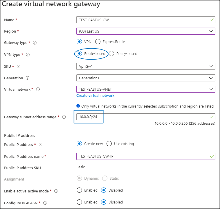
- Select or enter the following Create virtual network gateway options:
- Name: A name for the VNG.
- Region: Azure Region where the VNG will be active.
- Gateway type: VPN.
- VPN type: Route-based.
- SKU: VpnGw1.
- Virtual network: The Virtual Network (VNet) will have access to the VPN tunnel. Use the Create virtual network option if the VNet doesn't already exist.
- Gateway subnet address range: Azure pre-fills the lowest available subnet from the chosen VNet. Use the zero subnet if available.
- Public IP address: Create new or Use existing.
- Public IP address name: A name for the public IP address resource, if creating a new one.Note: Active-active mode and BGP ASN are disabled, as our discussion is focused on the tunnel security options (and not on HA setup or dynamic routing exchange).
- Proceed with creating the new VNG.Note: Deployment can take 20-30 minutes to complete.
VPN Connection and Local Network Gateway
Each Azure VPN tunnel is represented by a connection under its VNG. One VNG can service multiple tunnel connections. Unlike AWS, the public VPN gateway IP address in Azure is assigned to the gateway itself, as we saw in the VNG configuration discussed above. This is similar to a typical configuration in a physical VPN gateway device. The following steps show how to create a new connection and a local network gateway. The Local network gateway represents the remote network gateway and subnets, reachable through the tunnel.- Navigate to the VNG.
- Select Connections and click the Add button.
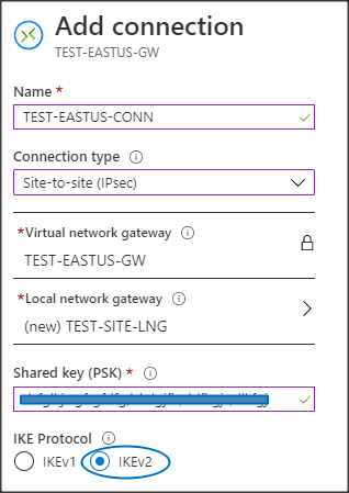
- Select or enter the following Add connection options:
- Name: A name for the new connection.
- Connection type: Site-to-site (IPsec).
- Virtual network gateway: The parent VNG is already selected (locked in).
- Shared key (PSK): The PSK that matches on both sides fo the tunnel. This can be an arbitrary string and you can modify it later if this info is unavailable.
- IKE Protocol: IKEv2
- Resource group: The resource group is already locked in.
- Go back up to the Local network gateway option and select Choose a local network gateway.
- Select Create new, which opens the Create local network gateway blade.
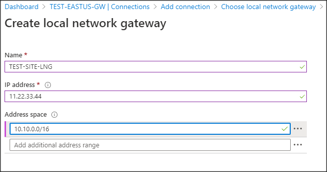
- Select or enter the following Create local network gateway options:
- Name: A name for the local network gateway.
- IP address: The remote location gateway public IP address.
- Address space: The remote subnet.Note: Azure creates an internal static route for this subnet pointed at this VPN connection.
- Click OK to save the options and go back to the Add connection blade.
- Click OK to create the new connection.
Remote Site VPN Tunnel Setup
We'll configure a route-based IKEv2 VPN tunnel on the remote site gateway device to work with the newly created Azure VPN tunnel. Because we're working with the default IPsec policies on the Azure side, you must make any customization on the remote site gateway side. Those Azure defaults dictate the options chosen on the remote side. Our example below shows the setup in a physical SonicWall firewall device, but the configuration is similar on devices from other manufacturers.VPN Security Policy
First, we'll create the VPN tunnel interface:- Navigate to the VPN -> Settings tab in the SonicWall GUI.
- Click Add to create a new VPN policy. This takes you to the General tab.
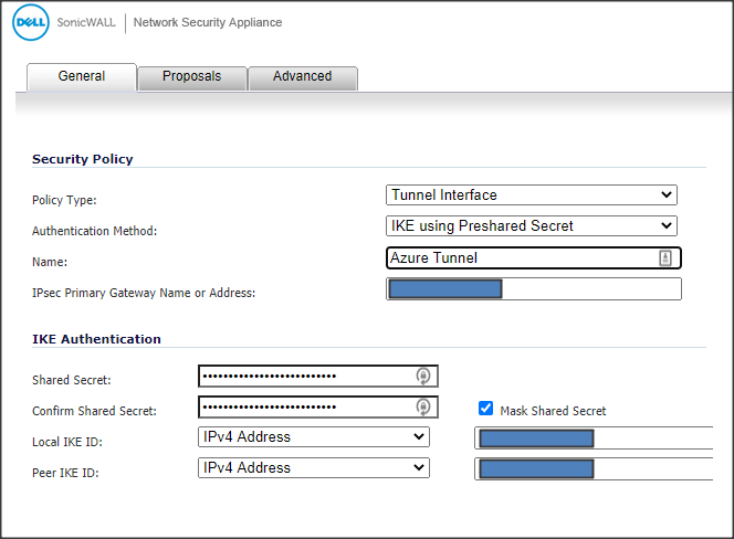
- Select or enter the following Security Policy options:
- Policy Type: Tunnel Interface.
- Authentication Method: IKE using Preshared Secret.
- Name: Name for the tunnel.
- IPsec Primary Gateway Name or Address: The Azure VNG public IP address.
- Select or enter the following IKE Authentication options:
- Shared Secret and Confirm Shared Secret: Matching the Azure PSK.
- Local IKE ID: The SonicWall public IP address (with IPv4 Address selected)
- Peer IKE ID: The Azure VNG public IP address (with IPv4 Address selected)
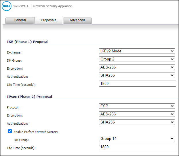
- Go to the Proposals tab.
- Select or enter the following IKE (Phase 1) Proposal options:
- Exchange: IKEv2 Mode.
- DH Group: Group 2.
- Encryption: AES-256.
- Authentication: SHA256.
- Life Time (seconds): 1800.
- Select or enter the following IPsec (Phase 2) Proposal options:
- Protocol: ESP.
- Encryption: AES-256.
- Authentication: SHA256.
- Enable Perfect Forward Secrecy: Enabled with DH Group set to Group 14.
- Life Time (seconds): 1800.
 Note: Phase 1 and 2 lifetime periods are much shorter than those default values on the Azure side (3600 seconds). This forces the Azure VNG to always be the responder during the negotiation stage which allows us to enable Perfect Forward Secrecy (PFS).
- Go to the Advanced tab.
- Leave Enable Keep Alive enabled.
- Enable the Do not send trigger packet during IKE SA negotiation option.
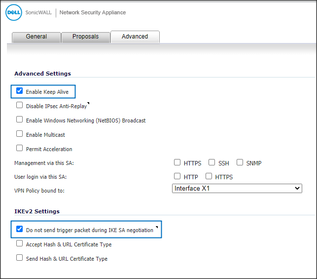
- Click OK to save the configuration.
Network Routing Policy
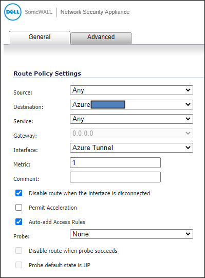
Now, you can create the necessary static route for the Azure-bound traffic.- Navigate to the Network-›Routing tab in the SonicWall GUI.
- Click Add to create a new Route Policy.
- Select the Azure network for Destination. Note: Best practice is to use a network address object for the destination. You might need to create the object prior.
- Set Interface to the VPN tunnel interface you just created.
- Click OK to create the static route.
Verification and Testing
In the Azure VNG, verify that the VPN connection status under Connections is Connected . In the remote site gateway SonicWall device, go to VPN -> Settings. Under the VPN Policies section verify the Azure VPN tunnel shows in green. In the Currently Active VPN Tunnels section you can monitor the traffic passing through. If necessary, test connectivity between the systems on both sides of the VPN tunnel.Site-to-Azure policy-based IKEv1 VPN tunnel
Some devices do not support route-based VPN tunnels, so one option is to create a new policy-based type Azure VNG to connect to those devices. However, because one Azure VNet can only connect to one VNG, this new VNG cannot connect directly to the needed VNet and additional peering and routing might be necessary. This could complicate the Azure configuration so a better solution might be to build a dedicated Azure VM that will act as a gateway. A VM running an IPsec application, such as Netgate pfSense (pfSense), can act as a VPN gateway on the Azure side. The information below demonstrates how you can set up a pfSense application running in a VM as a gateway. You'll use a physical Meraki MX firewall device that doesn't support IKEv2 (IKEv2 is supported in the beta firmware version for some Meraki MX models). You can replicate this on devices from other manufacturers that do not support IKEv2. The setup on the Meraki side dictates the level of security configured on both sides.Azure VPN Tunnel Setup
Netgate pfSense VM
First, you'll create a pfSense VM in Azure to serve as a VPN tunnel gateway. The following steps guide you through the setup:- Go to the Azure Marketplace and search for "pfsense" to find the Netgate pfSense® Firewall/VPN/Router app.
- In the app, create a virtual appliance.
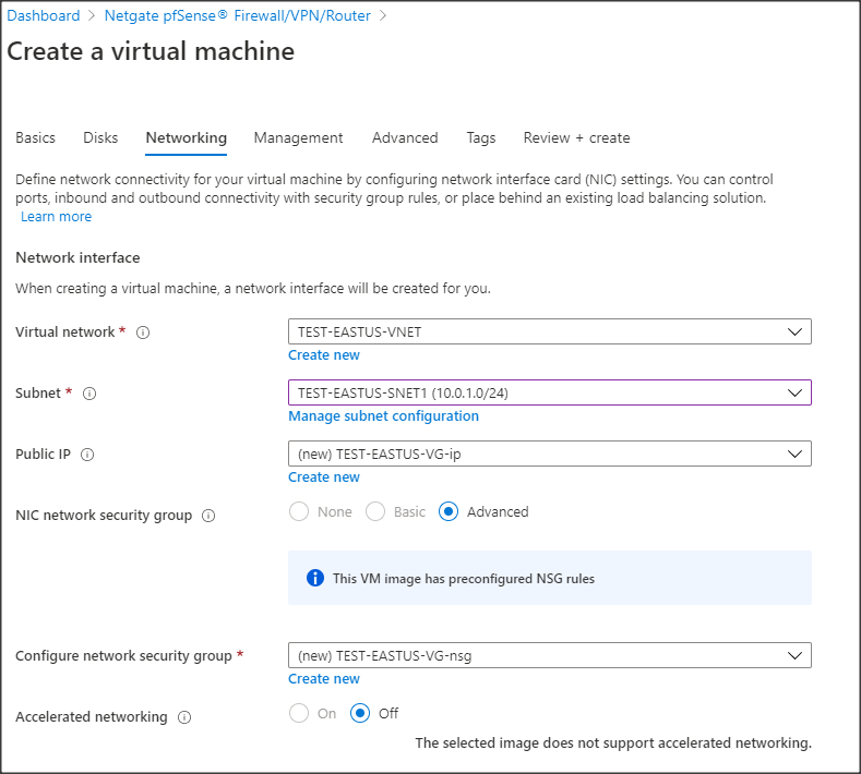
- Create the VM, selecting resources (vCPU, RAM, and disk) as you would normally do in Azure.Note: You can use minimal values for these resources during this step. You can increase them later depending on the actual traffic load.
- When choosing the Networking options, verify the network interface has the correct virtual network and subnet and that there is an assigned Public IP address:
pfSense VPN configuration
- When you create the VM and it's running, add a security rule in the VM Networking configuration to allow access from your public IP address on port 443.
- Browse to the pfSense public IP address on port 443. Use the username chosen during the VM creation and the default password pfsense to log in.
- When you are logged in, go to System -> User Manager and change the default password.
- Go to System -> Advanced -> Firewall&NAT and select the Disable Firewall option to disable all packet filtering. Note: pfSense can also act as a firewall in addition to the Azure security group configuration. Leave this option checked if your implementation requires it.
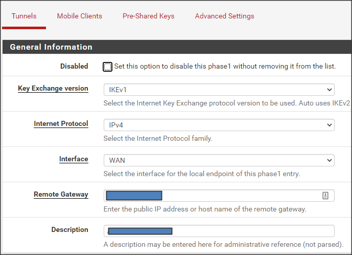
- Go to VPN -> IPsec -> Tunnels and select
 to create phase 1 of the VPN tunnel.
 - Select or enter the following General Information options:
- Key Exchange version: IKEv1.
- Internet Protocol: IPv4.
- Interface: WAN.
- Remote Gateway: The remote site gateway device public IP address.
- Description: A description for this VPN tunnel.
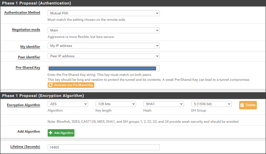
- Select or enter the following Phase 1 Proposal (Authentication) options:
- Authentication Method: Mutual PSK.
- Negotiation mode: Main.
- My identifier: My IP address.
- Peer identifier: Peer IP address.
- Click
 under the Pre-Shared Key field to generate a random PSK.
 - Select or enter the following Phase 1 Proposal (Encryption Algorithm) options:
- Algorithm: AES.
- Key length: 128 bits.
- Hash: SHA1.
- DH Group: 5 (1536 bit).
- Lifetime (Seconds): 14400.
- Click Save to finish setting up phase 1 of the VPN tunnel. This takes you back to the VPN -> IPsec -> Tunnels page.
- Click
 ->
->  to start the phase 2 VPN tunnel configuration.
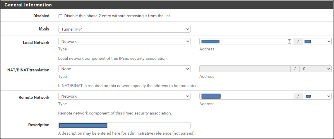
 - Select or enter the following General Information options:
- Mode: Tunnel IPv4.
- Local Network - Type: Network. Address: The Azure Vnet subnet.
- NAT/BINAT translation: None.
- Remote Network - Type: Network. Address: The remote site private subnet.
- Description: A description for this phase 2 tunnel.
- Select or enter the following Phase 2 Proposal (SA/Key Exchange) options:
- Protocol: ESP.
- Encryption Algorithms: AES 256 bits.
- Hash Algorithms: SHA1.
- PFS key group: 5 (1536 bit).
- Lifetime: 3600.
- (Optional) In the Advanced Configuration section, you can use the Automatically ping host option as a keep-alive ICMP test.
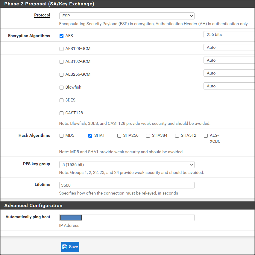
- Click Save to finish setting up this phase 2 VPN tunnel. This takes you back to the VPN -> IPsec -> Tunnels page.
- To create additional phase 2 VPN tunnels, you can use the configuration of the recently created one as a template:
- Click
 to show the phase 2 VPN tunnel you just created.
 - Click the copy icon/button in the P2 actions column.
- Repeat steps 12 through 15 by only changing the necessary values.
- Click
Route Table to pfSense VM
Because the pfSense gateway is not a typical VNG, Azure would not have created an internal static route needed to handle the traffic bound towards the remote site network. You need to create a routing table with a static route for that purpose.- Search for "route tables" in the Azure console search bar.
- Select Route tables.
- Click Add in the upper left corner of the Route tables display.
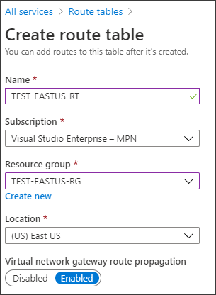
- Select or enter the following Create route table options:
- Name: A name for the route table.
- Resource group: The same as the pfSense VM VNet.
- Virtual network gateway route propagation: Enabled.
- When it's created, go to Settings -> Routes and click Add to create a route.
- Select or enter the following Add route options:
- Route name: A name for the route.
- Address prefix: The subnet of the remote site.
- Next hop type: Virtual appliance. This opens the next option.
- Next hop address: The private IP address of the pfSense VM interface.
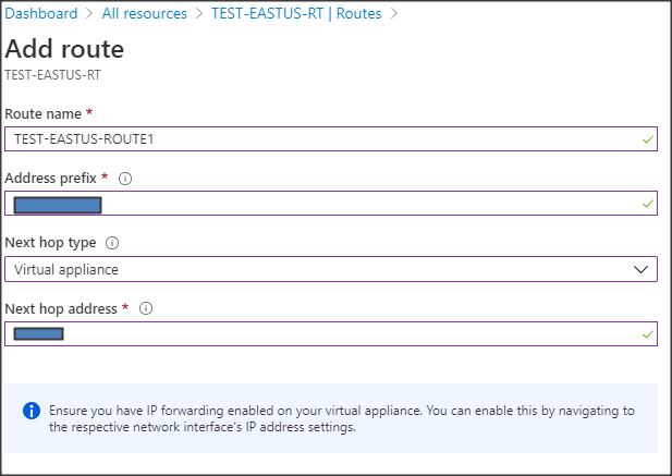 Note: As seen from the warning, the VM receives traffic not destined for its IP address, which would be normally dropped. Enabling IP forwarding in the next steps remedies this situation.
- Click OK to create the route.
- Repeat steps 5 through 7 to create any additional routes under this route table for each subnet on the remote site that needs to be reachable over the VPN tunnel.
- While still in the Route table view:
- Go to Settings -> Subnets and click Associate.
- Select the VNet and subnet where the pfSense VM is located.
- Click OK to save the association.Note: As needed, you can add additional subnets here in your particular setup.
- Locate the network interface configuration for the pfSense VM.
- Go to IP configurations under Settings.
- Enable the IP forwarding option.
Remote Site VPN Tunnel Setup
In the remote site gateway device, you'll configure a policy-based IKEv1 VPN tunnel to match settings implemented in the Azure pfSense VM. The following steps guide you through the setup:Meraki MX VPN Configuration
- In the MX Security Appliance, go to Security & SD-WAN-›Configure -> Site-to-site VPN -> Non-Meraki VPN peers.
- Select Hub (Mesh) for Type.
- Select the local subnets to include in the VPN tunnel policy.
- Click Add a peer.
- Enter a Name, following an established naming convention.
- Specify the public IP of the Azure pfSense VM for Public IP.
- Enter Private subnets. Those are all subnets on the Azure side that need to be reachable through the VPN tunnel.
- Select the Default link under IPsec policies, which opens a new window to set custom policy.
- Select or enter the following phase 1 options:
- Encryption: AES 128.
- Authentication: SHA1.
- Diffie-Hellman group: 5.
- Lifetime (seconds): 28800.
- Select or enter the following phase 2 options:
- Encryption: AES 256.
- Authentication: SHA1.
- PFS group: 5.
- Lifetime (seconds): 7200.
- When your done customizing, click Update.
- Enter the Preshared secret. You can retrieve the PSK by going back to VPN -> IPsec -> Tunnels of the pfSense GUI and editing the VPN tunnel. The PSK is in the Phase 1 Proposal (Authentication) section.
- Leave Availability set to All networks unless there is a security requirement to limit the access to the VPN tunnel from particular subnets.
- Click Save to complete the setup.
Verification and Testing
In the Azure pfSense GUI, go to Status -> IPsec -> Overview and verify the Status of the IPsec tunnel is . Click
to show the phase 2 (child SA) tunnel's status and verify that they've also been established.
Note: It's possible to have more than one child tunnel per remote subnet. In the remote site gateway Meraki device web UI, go to
Security appliance ->
VPN and click
Non-Meraki peer. Verify the VPN tunnel has a status of "green." In the pfSense web UI, the
Diagnostics-›
Ping page provides a way to test with ping. If necessary, test connectivity between machines on both sides of the VPN tunnel.
Note: If the VPN connection doesn't establish or is unstable, it might be necessary to change the security options (Encryption, Authentication, DH group, PFS) to less secure values. The same applies if the on-premises gateway device doesn't support the options used in the above examples.

